Cursed circuits #6: reverse avalanche oscillator
Cursed Circuits #6: The Reverse Avalanche Oscillator
"An oscillator so bad it's actually good."
In a previous installment, I discussed the notion that building an oscillator is easy it's actually quite hard to build an oscillator. While the internet is flooded with schematics, many are impractical, requiring exotic components or bizarre power rails, or they simply fail to function.
Today, we explore perhaps the most baffling "bad" oscillator you can construct with common parts: the Reverse Avalanche Oscillator.

The "Wrong" Way to Build It
At first glance, the circuit looks like a mistake. The NPN transistor is installed upside down, and the base terminal is left completely floating.

Despite this, the circuit functions perfectly. If you provide a supply voltage between and , the LED will begin to blink.
Observations
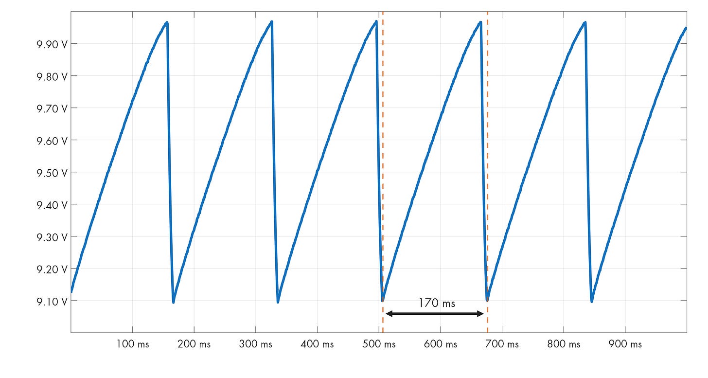
If you monitor the capacitor's terminals with an oscilloscope, you will observe a specific pattern:
- The capacitor charges up to approximately .
- It then rapidly discharges down to roughly .
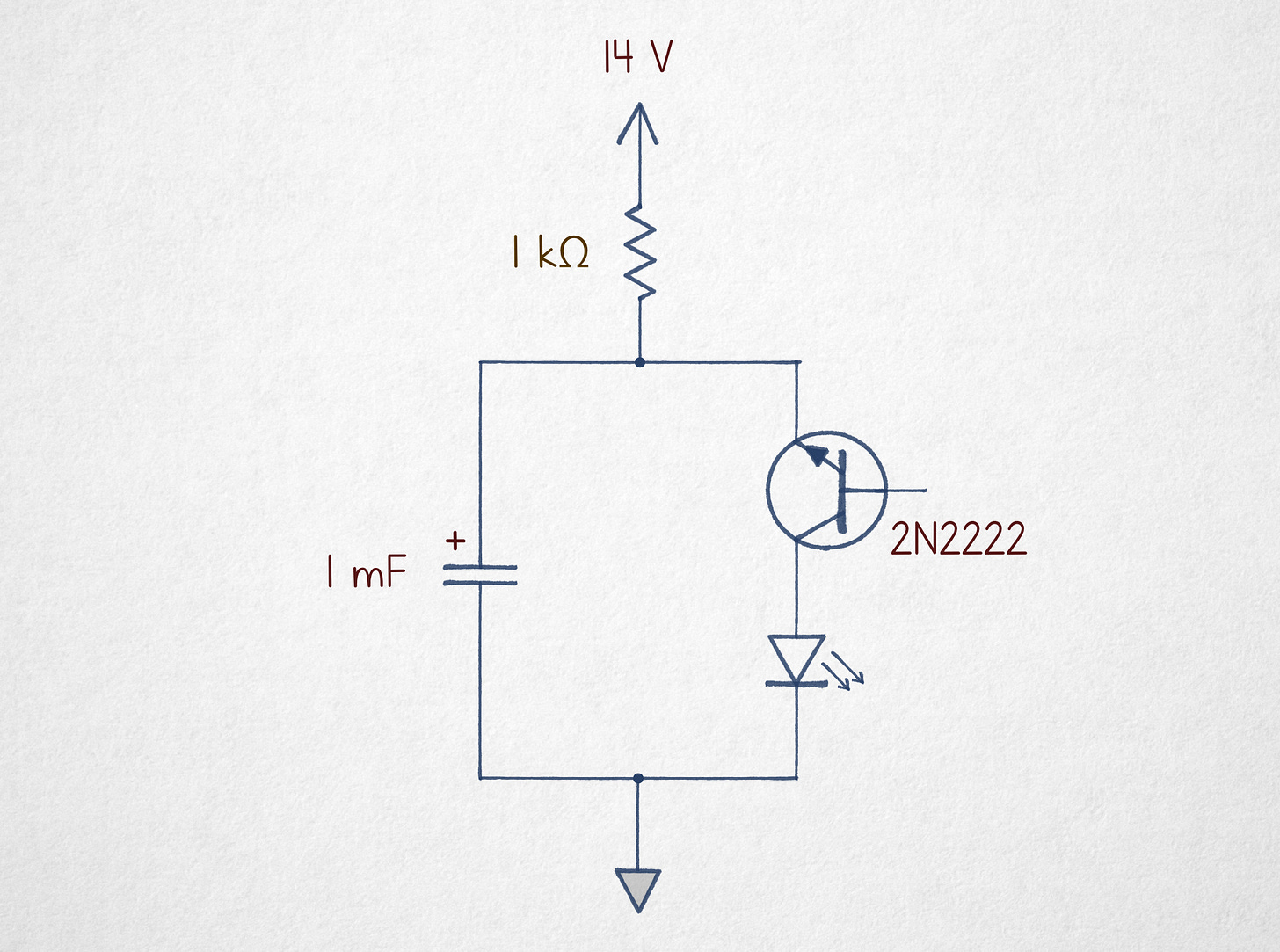
The mechanism is straightforward: the capacitor is charged via a 1 kΩ resistor from the positive rail and discharged through the inverted NPN transistor into the LED.
The Physics of the "Cursed" Junction
To understand why this works, we need to revisit semiconductor basics. If you need a refresher, check out How do transistors work, anyway?.
P-N Junction Recap
A standard diode is a p-n junction. The boundary between the p-type and n-type materials creates a depletion layer that prevents current flow.
- Forward Bias: A small positive voltage on the p-side collapses the depletion layer, allowing current to flow.
- Reverse Bias: The depletion region typically remains an impassable barrier.
However, if the reverse voltage becomes extreme, the electrostatic field becomes strong enough to accelerate charges, knocking electrons into the conduction band. This is known as avalanche breakdown.
The NPN Structure
An NPN transistor is essentially two conjoined diodes. Regardless of whether the collector or emitter is more positive, one junction is always reverse-biased. In a normal circuit, this prevents conduction. But this reverse-biased junction is susceptible to the avalanche effect.
The breakdown voltage depends heavily on the orientation:
| Orientation | Terminal Positive | Breakdown Voltage (2N2222) |
|---|---|---|
| Standard | Collector | |
| Reverse | Emitter |
The reason for this difference is that the emitter is more heavily doped (). A more heavily doped semiconductor creates a thinner depletion region, which is much easier to disrupt.
Why it Oscillates (The V-I Curve)
A simple reverse-biased diode wouldn't oscillate; it would just reach a stable equilibrium where the charging current equals the discharge current. The "magic" here lies in the specific V-I characteristic of a reverse-biased NPN with a floating base.
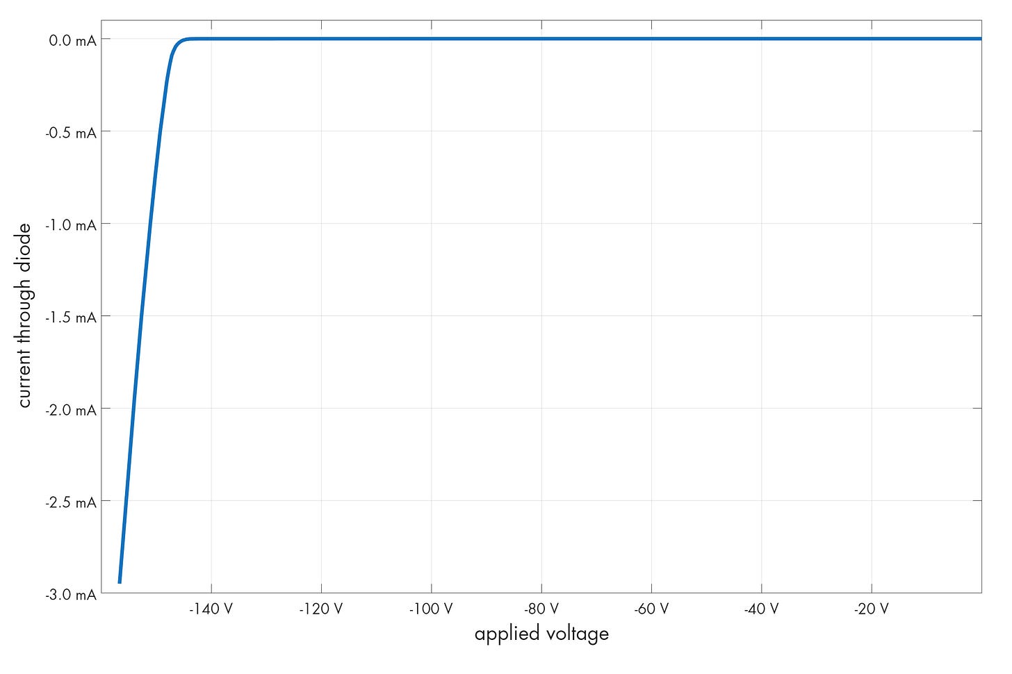
The structure stays non-conductive until about . Once it clears this "hump," the conduction path opens further as more current is pushed through. For example:
- At , it needs to maintain conduction.
- At , it only needs .
The Oscillation Cycle
This creates a state where stable equilibrium is impossible:
Historical Parallels and Conclusions
This behavior is reminiscent of the neon lamp. A neon lamp requires a high "striking voltage" to ionize the gas, but once the plasma is established, the sustaining voltage is much lower. You can build a similar oscillator with a neon lamp, though it requires higher voltages, larger capacitors, and suffers from poor stability.
Summary Checklist
- Use an NPN transistor (e.g.,
2N2222) - Install it in reverse (Emitter to positive)
- Leave the base floating
- Supply to
Ultimately, this circuit serves as a reminder that semiconductors are complex. We are utilizing a specific region of the V-I curve that is almost never mentioned in textbooks.
Further Reading in the Cursed Series:


// Conceptual logic of the oscillator
while (power_on) {
    capacitor.charge(via_resistor);
    if (capacitor.voltage >= 8.2) {
        transistor.avalanche_breakdown();
        capacitor.discharge(via_led);
    }
}