Hot Chips 2026: Applying High Bandwidth Flash (HBF)
Hot Chips 2026: Exploring the Implementation of High Bandwidth Flash (HBF)
Modern machine learning (ML) workloads are characterized by an insatiable demand for DRAM capacity. To address this, a new concept was presented at the Hot Chips 2026 tutorials day by Anurag Agarwal and Radhakrishna Giduthuri: High Bandwidth Flash (HBF).

What exactly is HBF?
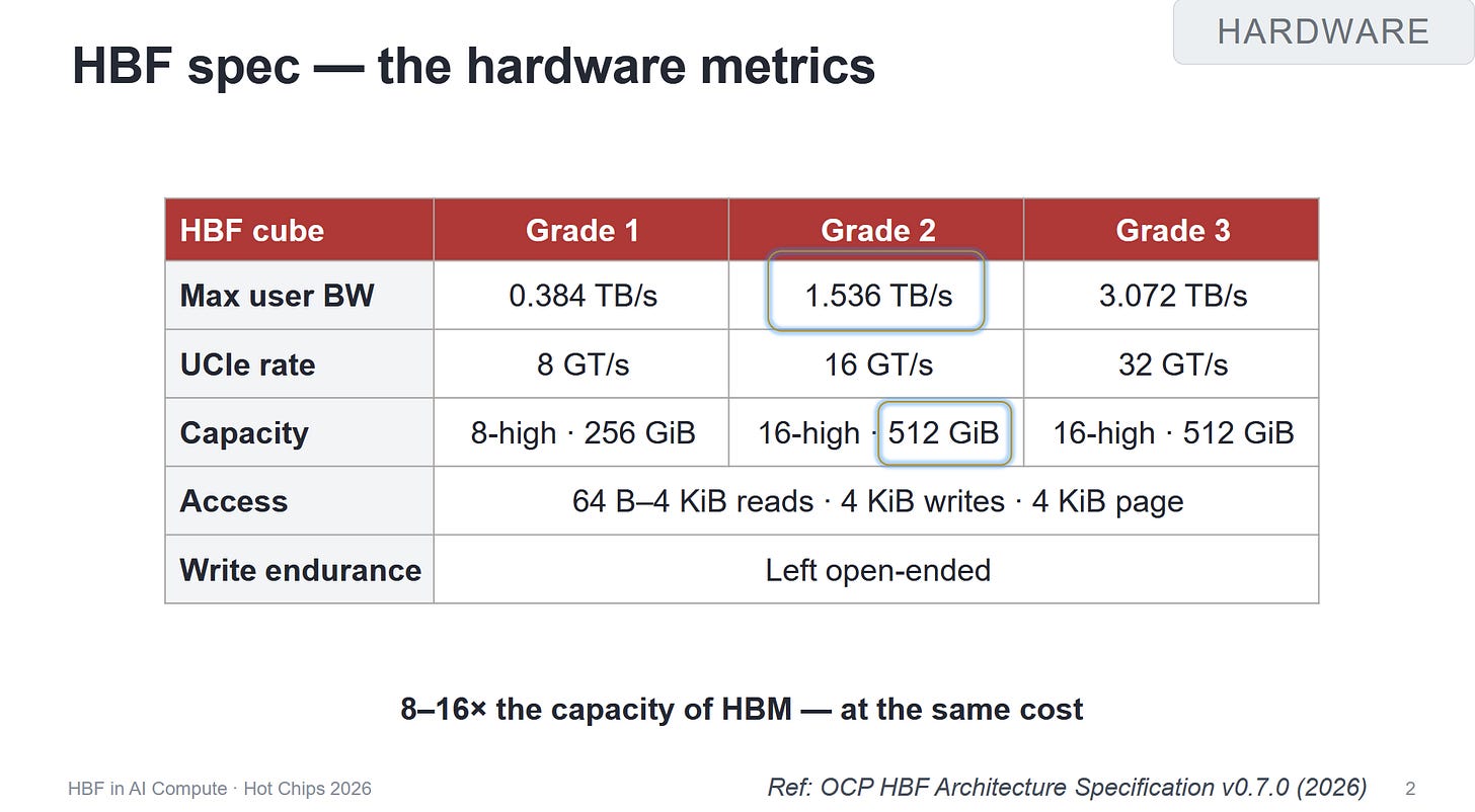
At its core, HBF utilizes the same flash memory technology found in contemporary SSDs. However, the implementation is radically different. While a standard SSD sits on a PCIe bus, HBF is designed using a form factor similar to High Bandwidth Memory (HBM).
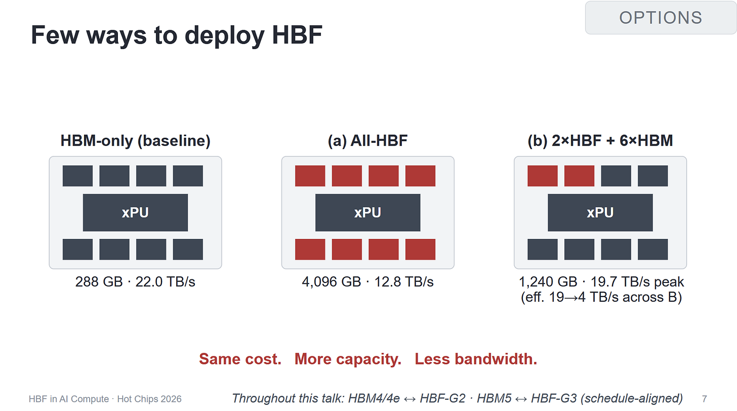
Essentially, HBF "cubes" are integrated directly onto the compute chip's package, potentially residing right alongside HBM. The goal is to bridge the gap between the extreme speed/low capacity of HBM and the slow speed/high capacity of traditional storage.
HBM vs. HBF: A Quick Comparison
| Feature | HBM (High Bandwidth Memory) | HBF (High Bandwidth Flash) |
|---|---|---|
| Technology | DRAM | Flash (NAND) |
| Capacity | Relatively Low | Very High |
| Bandwidth | Extremely High | Moderate/Decent |
| Access | Byte-addressable | Block-aligned chunks |
| Location | On-package | On-package |
The Technical Reality: Not Just Faster RAM
It is a mistake to view HBF as a pool of system memory (similar to how Intel's Optane was marketed). Instead, HBF is effectively an SSD integrated directly onto the processor.
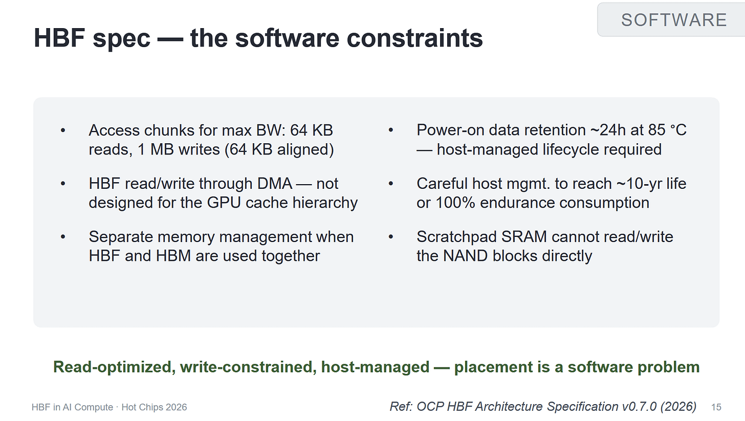
Because it is flash-based, it cannot handle fine-grained random access. All interactions must occur in large, aligned chunks. This shifts a massive burden onto the host software, which must now manage:
- Write leveling
- Data retention
- Block-aligned I/O operations
"Taking advantage of HBF means formulating a special strategy and implementing it into a runtime."
Applying HBF to ML Workloads
The presentation focused on simulations and projections, as no physical HBF products are currently available. Two primary use cases were explored:
1. Optimizing the KV Cache in vLLM
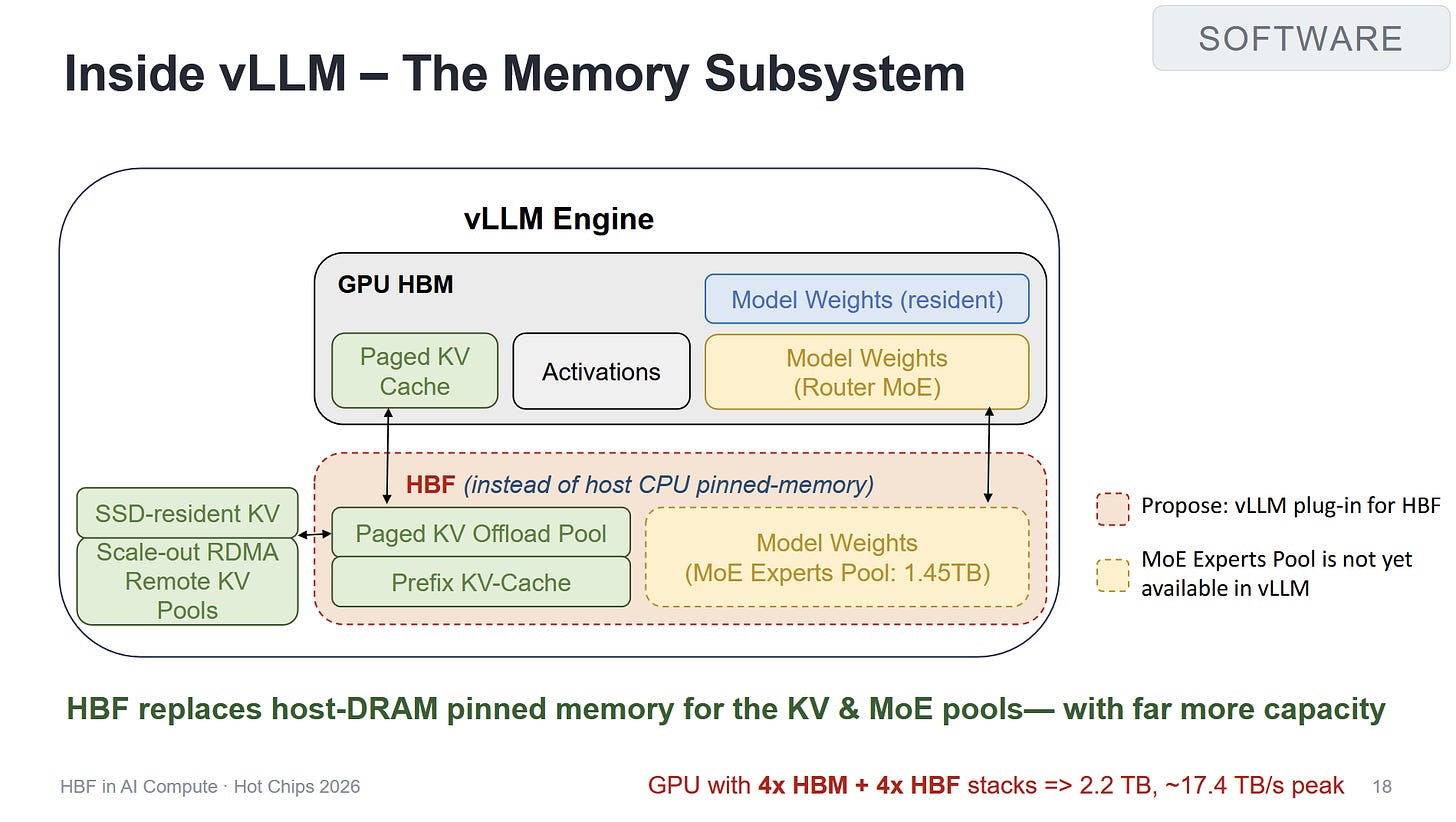
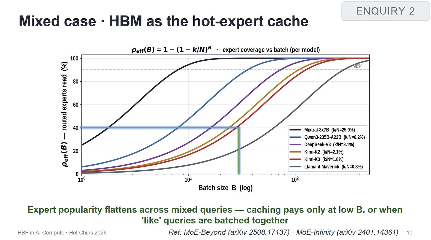
vLLM currently stores model weights in GPU memory and is seeking ways to lower VRAM usage (such as using pinned CPU memory). While HBF's lack of random access makes simple weight-swapping difficult, it could work for sparse attention.
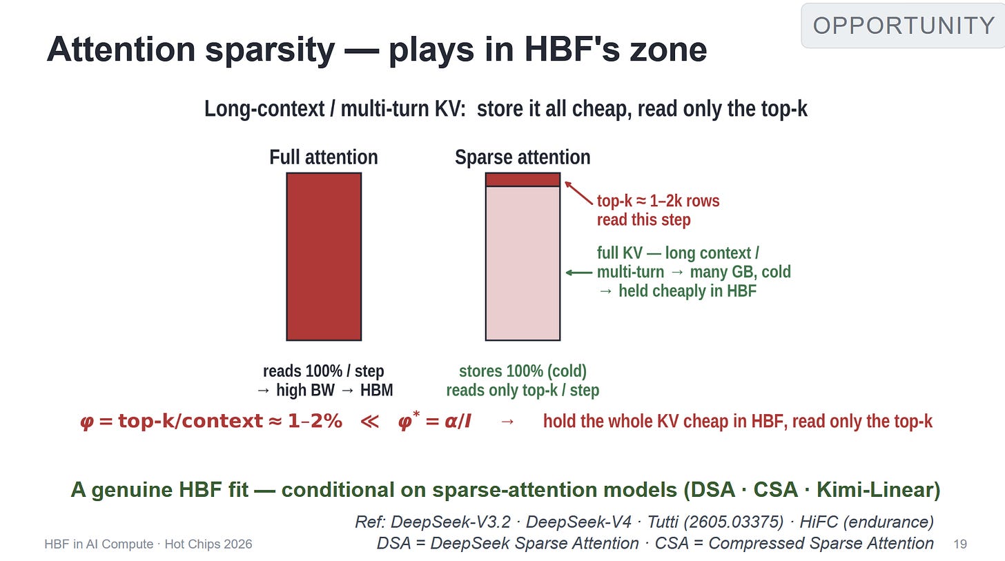
In sparse attention, only a small subset of tokens is read from the top of the KV cache. This allows the bulk of the cache to remain "cold" in the HBF, utilizing its massive capacity without overloading its limited bandwidth.
- The Challenge: Top-k reads are often scattered, but HBF prefers sequential access.
- The Solution: Use DMA (Direct Memory Access) to move top-k rows into DRAM as needed.
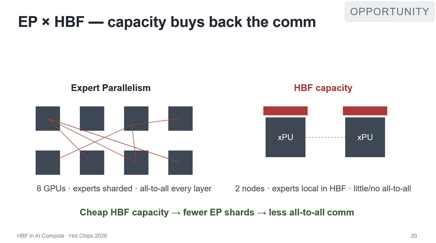
2. Reducing Cross-Device Communication
When large models are sharded across multiple GPUs, the bottleneck is often the "scatter and gather" operations across the interconnect rather than the compute power itself.
HBF can mitigate this by allowing each GPU to store more replicated weights locally. While reading from flash via DMA is slower than DRAM, it is significantly faster than fetching data from another device over a network or bus.
The Economic Equation
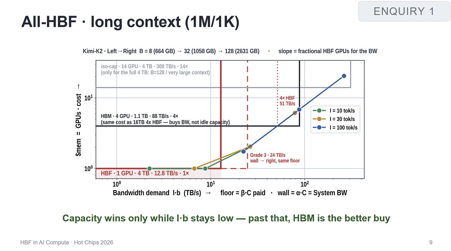
Agarwal noted that HBF's viability depends on whether a workload is bandwidth-bound. We can think of the cost efficiency as a relationship between capacity and bandwidth:
HBF wins decisively on , but loses to HBM on . If a workload hits a bandwidth wall, the cost-per-token efficiency plummets.
Final Analysis and Software Hurdles
The author, Chester Lam, expresses skepticism regarding the software effort required. Managing HBF is akin to using low-level disk APIs that bypass the OS cache, such as:
O_DIRECT(Linux)FILE_FLAG_NO_BUFFERING(Windows)
If you want to change a single byte, you cannot simply overwrite it. You must:
- Read a large block (e.g., 64 KB) into DRAM.
- Modify the byte.
- Write the entire block back to flash.
// Conceptual HBF Write Operation
void hbf_write_byte(uint64_t address, uint8_t value) {
    uint8_t buffer[65536]; // 64KB Block
    dma_read_hbf(address & ~0xFFFF, buffer); // Align to block
    buffer[address & 0xFFFF] = value;        // Modify
    dma_write_hbf(address & ~0xFFFF, buffer); // Write back
}
The effort to rewrite frameworks for HBF might be nearly identical to the effort required to simply stream weights from a high-speed NVMe SSD. While the OS kernel can abstract these difficulties via buffering, doing so would negate the performance benefits of the HBF's proximity to the chip.
Community Note: The Write Amplification Nightmare
A reader (James) pointed out that the "64 KB block" issue is actually far worse due to write amplification. If writes are defined in 1 MB blocks, modifying a single 64 KB chunk requires reading the target chunk plus 15 additional chunks, modifying one, and writing the entire 1 MB block back. This is a classic failure point when attempting to use flash as a RAM substitute.
